
Flow Chemistry Equipment
Due to the continuous operation of flow chemistry, their are different types and requirements for equipment when compared to batch reactions. Some commonly used pieces of equipment and their symbols are shown below. A flow-diagram (or Process and Instrumentation Diagram - P&ID) shows how your reactor scheme is assembled and an important part of describing your process. Reaction conditions are also important and covered next.
Common flow symbols and equipment
| Symbol | Description |
|---|---|
 | Pump: drives flow of fluid into reactor. Common pumps include syringe pumps, gear pumps, HPLC pumps and peristaltic pumps. Considerations include flow rate, pressure, suspended solids and fluid viscosity. |
 | Pipe: carries fluid between flow equipment. Common tubing in laboratory flow chemistry is 1/8” outer diameter (OD) tubing and 1/16” OD tubing manufactured from PTFE. This fits standard 1/4-28 HPLC fittings. However it is the inner diameter (ID)that is relant to the performance of the reactor - so ensure you report this as tubing with the same outer diameter can have different inner diameters. |
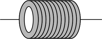 | Tubular reactor: coil of tubing in which reaction takes place. For single phase chemistry, mixing is largely controlled by diffusion. Low energy input means phases segregate - e.g. particles settle. |
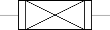
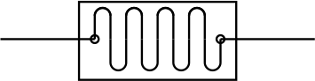
 | Inline mixer: tortuous path through a tubular reactor (often using inserts) to create mixing. |
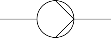
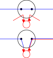
 | Mixing tee and mixing cross: used to mix reagents before entering reaction zones - the internal flow may have been designed to give mixing between streams. For very fast reactions these can form the reactor itself. |
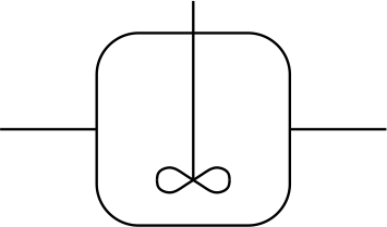 | Continuous Stirred Tank Reactor (CSTR): single stirred tank reactor with fluid entrances and exits. Energy input through active mixing allows multiphasic reactions to be carried out. |
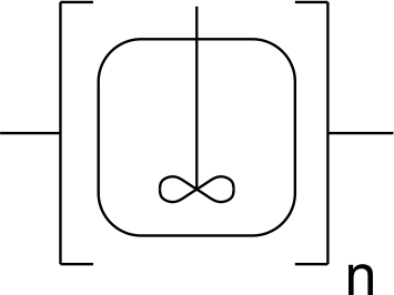 | Cascade CSTR: a chain of n CSTRs to give consistent processing conditions. Multiple zones also allows addition of reactants into different zones and instrumentation between zones. Well understood behaviour and the technology that the fReactors are built on. |
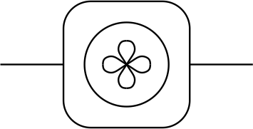 | A single fReactor module bringing the benefits of a CSTR to the laboratory environment. |
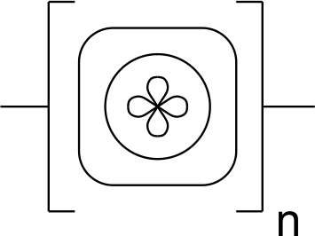 | A cascade of n fReactors: a chain of n fReactors - our laboratory version of CSTRs bringing the benefits of these to your laboratory environment. |
 | Packed bed: a fixed bed of particles (e.g. catalyst) through which the liquid flows. |
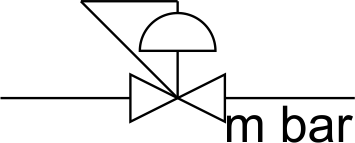 | Back pressure regulator: a spring loaded valve to maintain an elevated pressure within the reactor – thereby allowing operation at higher temperature. The pressure differential is indicated e.g. a BPR of 7 bar (indicate where m is) means the reactor pressure will be 8 bar (absolute) if the outlet is open to atmospheric pressure. |
 | Micro-reactor: generally consists of sub-millimetre flow channels etched into a small chip. Small distances mean diffusion can be efficient for mixing and high surface area to volume ratio - if your process relies on these scale-out (numbering up) rather than scale-up might be the path to larger scale production. |
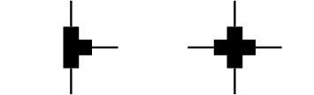
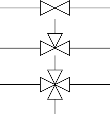 | Valves: used to divert flow from one pipe to another and to switch off flow. Shown left are 2-way, 3-way and 4-way valves. |
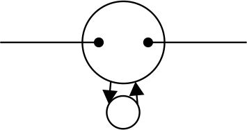 |  An injection loop allows a sample to be stored (or collected) in a loop of pipe known the storage loop, before being injected (or extracted) from the main flow. Further information is on this page. An injection loop allows a sample to be stored (or collected) in a loop of pipe known the storage loop, before being injected (or extracted) from the main flow. Further information is on this page. |
 | Instrumentation: allows you to characterise properties - inline sensors give a direct read of the flowing stream (e.g. an inserted temperature probe), atline is characterised by a sample being withdrawn (e.g. into a HPLC). Common inline sensors include temperature, pH, UV absorption; atline sensors include HPCL, mass-spectrometry. |