Laminar Flow Reactors
 Before examining the RTD of a tubular reactor, it is useful to understand the flow patterns within such a device.
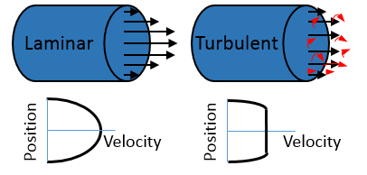
Within the pipe, there are two types of flow structures- 'turbulent' and 'laminar'. In most laboratory situations, the flow in a tubular flow reactor is laminar - at the pipe wall the molecules next to the solid surface are stationary and as you move to the centre of the pipe, away from this interaction, the velocity increases. You can confirm which regime the flow is operating in by calculating the Reynolds Number - less than 2300 and the flow is laminar, more than 4000 the flow is turbulent (between these the flow flips from one regime to another). A much simpler flow model you may see is referred to as the plug flow model (and from comes the commonly used term plug flow reactor). Here flow is assumed to moving at the same velocity all the way across the pipe - this doesn't acknowledge the real flow patterns; to put it another way, the flow within most tubular reactors isn't plug flow and calling it this is confusing!
Typical viscosities (20°C): water 1mPa.s ; light oil 5-10mPa.s ; olive oil 100mPa.s ; glycerol (pure) 1412 mPa.s
Recognizing the flow within a tubular reactor will help you better understand the residence time distributions within such reactors. But if there is one thing to take away from this is that a tubular reactor is NOT operating in a plug flow regime, best not to confuse yourself by calling it a plug flow reactor!
Notes: Pressure drops are calculated assuming smooth pipes. Below Re=2000, flow is assumed to be laminar and pressure drop calcluated using Hagen–Poiseuille law. For Re>2000, flow is assumed to be turbulent, and the friction factor calculated using the expression from Colebrook, C. F., Turbulent Flow in Pipes, With Particular Reference to the Transition Region Between the Smooth and Rough Pipe Laws, Inst. Civ. Eng., London, Vol. 11, 1939, pp. 133-156. In all cases, the fluid is taken to be Newtonian.
