Sample loops
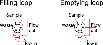
 The two images show fluid being charged into the loop, before being switched into the main flow. In the lefthand image, whilst the main flow (blue) is running, the loop can be accessed to charge it with a second fluid (red). This can then be switched into the main flow which pushes the sample out of the loop, as shown in the righthand image.
 The sample loop is generally constructed using a 6 way valve. The 6 ports are distributed around the circumference of the valve and are joined either to the port located clockwise or anticlockwise from themselves. Switching the valve changes the neighbouring port they are connected to. The figure to the right shows how the sample loop is physically connected across the valve. The left image shows the sample being charged into the loop, and the right shows how this can be switched into the flow. Alternatively you could start with the flow passing through the loop (righthand image), and then switch the loop out of the main flow before collecting the sample through the waste port (lefthand image).
One last thing - it is well worth you understanding the basics of residence time distribution for laminar pipe flow reactors to understand why the fluid exiting the loop will be at a different concentration than the fluid originally within the loop due to the hydrodynamics of the flow.
